
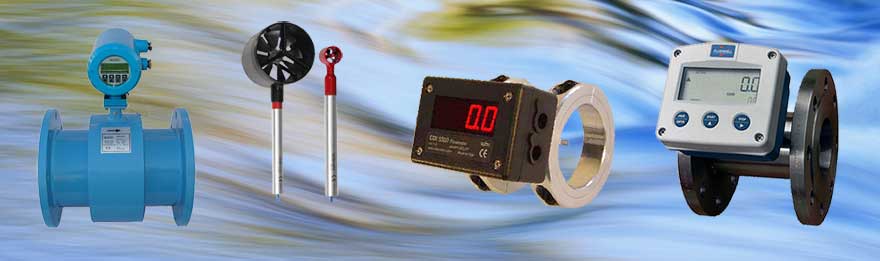
Flow Measuring Instruments, Measurement & Analysis Instruments
Flow Measuring Instruments
Dec
Flow Measuring Instruments
Flow measurement
is the quantification of bulk fluid movement. Flow can be measured in a variety of ways. The common types of flowmeters with industrial applications are listed below:
- a) Obstruction type (differential pressure or variable area)
- b) Inferential (turbine type)
- c) Electromagnetic
- d) Positive-displacement flowmeters, which accumulate a fixed volume of fluid and then count the number of times the volume is filled to measure flow.
- e) Fluid dynamic (vortex shedding)
- f) Anemometer
- g) Ultrasonic
- h) Mass flowmeter (Coriolis force).

Flow measurement methods other than positive-displacement flowmeters rely on forces produced by the flowing stream as it overcomes a known constriction, to indirectly calculate flow. Flow may be measured by measuring the velocity of fluid over a known area. For very large flows, tracer methods may be used to deduce the flow rate from the change in concentration of a dye or radioisotope.
flow meter (or flow sensor) is an instrument used to measure linear, nonlinear, mass or volumetric flow rate of a liquid or a gas. When choosing flowmeters, one should consider such intangible factors as familiarity of plant personnel, their experience with calibration and maintenance, spare parts availability, and mean time between failure history, etc., at the particular plant site. It is also recommended that the cost of the installation be computed only after taking these steps.
One of the most common flow measurement mistakes is the reversal of this sequence: instead of selecting a sensor which will perform properly, an attempt is made to justify the use of a device because it is less expensive. Those “inexpensive” purchases can be the most costly installations. This page will help you better understand flow meters, but you can also speak to our application engineers at anytime if you have any special flow measurement challenges.
First Steps to Choose the Right Flow Meter
The first step in flow sensor selection is to determine if the flowrate information should be continuous or totalized, and whether this information is needed locally or remotely. If remotely, should the transmission be analog, digital, or shared? And, if shared, what is the required (minimum) data-update frequency? Once these questions are answered, an evaluation of the properties and flow characteristics of the process fluid, and of the piping that will accommodate the flowmeter, should take place. In order to approach this task in a systematic manner, forms have been developed, requiring that the following types of data be filled in for each application: Download the Flowmeter Evaluation Form.
Fluid and flow characteristics
The fluid and its given and its pressure, temperature, allowable pressure drop, density (or specific gravity), conductivity, viscosity (Newtonian or not?) and vapor pressure at maximum operating temperature are listed, together with an indication of how these properties might vary or interact. In addition, all safety or toxicity information should be provided, together with detailed data on the fluid’s composition, presence of bubbles, solids (abrasive or soft, size of particles, fibers), tendency to coat, and light transmission qualities (opaque, translucent or transparent?).
Pressure & Temperature Ranges
Expected minimum and maximum pressure and temperature values should be given in addition to the normal operating values when selecting flowmeters. Whether flow can reverse, whether it does not always fill the pipe, whether slug flow can develop (air-solids-liquid), whether aeration or pulsation is likely, whether sudden temperature changes can occur, or whether special precautions are needed during cleaning and maintenance, these facts, too, should be stated.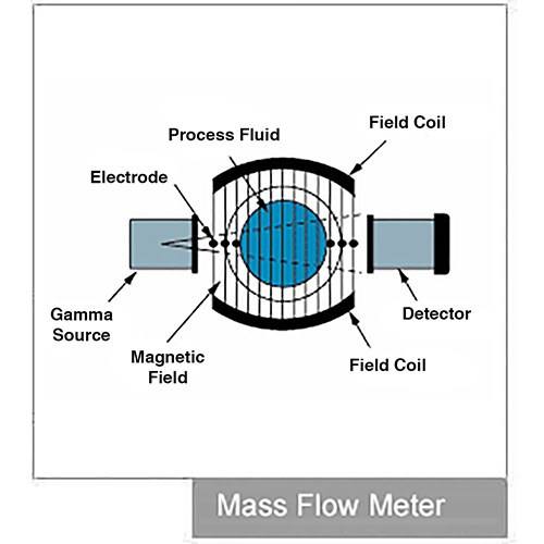
Piping and Installation Area
Concerning the piping and the area where the flowmeters are to be located, consider: For the piping, its direction (avoid downward flow in liquid applications), size, material, schedule, flange-pressure rating, accessibility, up or downstream turns, valves, regulators, and available straight-pipe run lengths. The specifying engineer must know if vibration or magnetic fields are present or possible in the area, if electric or pneumatic power is available, if the area is classified for explosion hazards, or if there are other special requirements such as compliance with sanitary or clean-in-place (CIP) regulations.
Flow rates and Accuracy
The next step is to determine the required meter range by identifying minimum and maximum flows (mass or volumetric) that will be measured. After that, the required flow measurement accuracy is determined. Typically accuracy is specified in percentage of actual reading (AR), in percentage of calibrated span (CS), or in percentage of full scale (FS) units. The accuracy requirements should be separately stated at minimum, normal, and maximum flowrates. Unless you know these requirements, your flowmeter’s performance may not be acceptable over its full range.
In applications where products are sold or purchased on the basis of a meter reading, absolute accuracy is critical. In other applications, repeatability may be more important than absolute accuracy. Therefore, it is advisable to establish separately the accuracy and repeatability requirements of each application and to state both in the specifications.
When a flowmeter’s accuracy is stated in % CS or % FS units, its absolute error will rise as the measured flow rate drops. If meter error is stated in % AR, the error in absolute terms stays the same at high or low flows. Because full scale (FS) is always a larger quantity than the calibrated span (CS), a sensor with a % FS performance will always have a larger error than one with the same % CS specification. Therefore, in order to compare all bids fairly, it is advisable to convert all quoted error statements into the same % AR units.
Flow Measurement in HistoryOur interest in the measurement of air and water flow is timeless. Knowledge of the direction and velocity of air flow was essential information for all ancient navigators, and the ability to measure water flow was necessary for the fair distribution of water through the aqueducts of such early communities as the Sumerian cities of Ur, Kish, and Mari near the Tigris and Euphrates Rivers around 5,000 B.C.
In well-prepared flow meter specifications, all accuracy statements are converted into uniform % AR units and these % AR requirements are specified separately for minimum, normal, and maximum flows. All flowmeters specifications and bids should clearly state both the accuracy and the repeatability of the meter at minimum, normal, and maximum flows.
Accuracy vs. Repeatability
If acceptable metering performance can be obtained from two different flow meter categories and one has no moving parts, select the one without moving parts. Moving parts are a potential source of problems, not only for the obvious reasons of wear, lubrication, and sensitivity to coating, but also because moving parts require clearance spaces that sometimes introduce “slippage” into the flow being measured. Even with well maintained and calibrated meters, this unmeasured flow varies with changes in fluid viscosity and temperature. Changes in temperature also change the internal dimensions of the meter and require compensation.
Furthermore, if one can obtain the same performance from both a full flowmeter and a point sensor, it is generally advisable to use the flowmeter. Because point sensors do not look at the full flow, they read accurately only if they are inserted to a depth where the flow velocity is the average of the velocity profile across the pipe. Even if this point is carefully determined at the time of calibration, it is not likely to remain unaltered, since velocity profiles change with flowrate, viscosity, temperature, and other factors.
Mass or Volumetric Units
Before specifying a flow meter, it is also advisable to determine whether the flow information will be more useful if presented in mass or volumetric units. When measuring the flow of compressible materials, volumetric flow is not very meaningful unless density (and sometimes also viscosity) is constant. When the velocity (volumetric flow) of incompressible liquids is measured, the presence of suspended bubbles will cause error; therefore, air and gas must be removed before the fluid reaches the meter. In other velocity sensors, pipe liners can cause problems (ultrasonic), or the meter may stop functioning if the Reynolds number is too low (in vortex shedding meters, RD > 20,000 is required).
In view of these considerations, mass flowmeters, which are insensitive to density, pressure and viscosity variations and are not affected by changes in the Reynolds number, should be kept in mind. Also underutilized in the chemical industry are the various flumes that can measure flow in partially full pipes and can pass large floating or settleable solids.
Fluid Flow Instrumentation
In the physical world, mechanical engineers are frequently required to monitor or control the flow of various fluids through pipes, ducts and assorted vessels. This fluid can range from thick oils to light gasses. While some techniques work better with some groups of fluids, and less well with others, some are not at all suitable for some applications. In this primer on fluid flow instrumentation we will look at a wide variety of flow transducers and their application in the physical world.
1.0 Fluid flow measurement
Fluid flow measurement can encompass a wide variety of fluids and applications. To meet this wide variety of applications the instrumentation industry has, over many years, developed a wide variety of instruments. The earliest known uses for flow come as early as the first recorded history. The ancient Sumerian cities of UR and Kish, near the Tigris and Euphrates rivers (around 5000 B.C.) used water flow measurement to manage the flow of water through the aqueducts feeding their cities. In this age the a simple obstruction was placed in the water flow, and by measuring the height of the water flowing over the top of the obstruction, these early engineers could determine how much water was flowing. In 1450 the Italian art architect Battista Alberti invented the first mechanical anemometer. It consisted of a disk placed perpendicular to the wind, and the force of the wind caused it to rotate. The angle of inclination of the disk would then indicate the wind velocity. This was the first recorded instrument to measure wind speed. An English inventor, Robert Hooke reinvented this device in 1709, along with the Mayan Indians around that same period of time. Today we would look down our noses at these crude methods of flow measurement, but as you will see, these crude methods are still in use today.
1.1 Types of flow measurement devices
Fluid flow devices fall into a number of device categories as well as fluid classes. In general we can split the fluids into two classes; gasses and liquids. Within these two broad classes are a number of special classes that one should be careful of. Flammable liquids and gasses require special handling, as do those that are at temperature extremes (cold or hot). When selecting a transducer you should be cautious that the device you are selecting is compatible with the fluid and conditions you hare working with. A few examples would be acids, food grade liquids, and DI water. Surprisingly de-ionized water is an extremely harsh liquid that can cause serious headaches.
The physical measurement devices come in a number of classifications. While the following classifications do not match any industry standards, they serve to break the transducers down into some reasonably functional groups. These are:
Obstruction flow meters
Velocity flow meters – Including Moving Member meters Positive Displacement meters
Variable area meters
Electronic meters
We will spend some time at each category, looking at the particular devices that fall into that category. Some of these devices will work with a wide array of fluids, while others have significant limitations. This tutorial should help you understand what these restrictions are and when to use or not use a particular meter.
2.0 Obstruction flow meters
Obstruction flow meters are the simples and oldest of the measurement classes. One of the first obstruction flow meters was used by the ancient Samarians. In order to measure the amount of water flowing through an aquaduct, they would place a board across the flow, and measure how high the water was when it flowed over the top of the board. In this way they could easily calculate how much water was flowing in the duct. This was modified in later times to a device called a “notch” weir.
2.1 Notch weir
Notch weirs are classified by the shape of their notch; rectangular weirs; triangular, or Vnotch, weirs; trapezoidal weirs; and parabolic weirs.
The picture above shows a V-notch weir. The edge the water cascades over is called the crest and the overflowing water sheet is called the nappe. Today weirs are still used to determine flows from open water sources such as streams. A typical 90° V-notch will be beveled at 45° so the edge is less than 0.08” thick, and the angle of the notch will be precisely 90°. Water flow over the weir is calculated by the equation : Q=2.49h12.48 , where h1 = head on the weir in ft and Q = discharge over weir in ft3/s.
It is easy to see that this is a simple measurement technique can be used on nearly any open flowing body of water. Its simply a matter of building a large enough weir plate. It is just as obvious that this technique wont work in an enclosed pipe, and it certainly wont work for gasses. The measurement of head is the height of the water above the lowest portion of the weir, and should be made at least four times that height, back from the weir.
2.2 Orifice plate
The equivalent of the notch weir in a tube would be an orifice plate. This flow device is created by inserting an obstructing plate, usually with a round hole in the middle, into the pipe and measuring the pressure on each side of the orifice. This is again a very simple device that has been in use for measuring both gas flow and liquid flow for decades.
These plates are generally installed by trapping it between two pipe flanges. Pressure taps on each flange allow you to easily measure the pressure differential across the plate. This pressure differential, along with the dimensions of the plate, are combined with certain fluid properties to determine the flow through the pipe.
The calculation for incompressible (liquid) flow is described by the incompressible Bernoulli equation, as long as the flow is sub-sonic ( < mach 0.3).
∆P=ρV22 −ρV12
Given the following physical layout, you can modify this formula to take into account the dimensional information rather than the velocity. Also the equation above assumes
to the equation called a discharge coefficient (Cd ). The resulting equation shows how the area and this new coefficient are applied to get a flow rate (Q).
Q=Cd
Since the actual flow profile at location 2 (downstream) is quite complex, making the effective value of A2 uncertain, a substitution is made and a new coefficient Cf is put in place of the area and Cd. The new equation looks like:
Q=C f A o 2 ∆P ρ
As you can see the formula has been simplified significantly, now only requiring the value of Cf, the area of the orifice (Ao), the density of the fluid and the differential pressure to obtain the volumetric flow rate. The only problem now is the value of Cf. The flow coefficient is found experimentally and is tabulated in numerous reference books. This value ranges from 0.6 to 0.9 for most orifices, and the value depends on the orifice and pipe diameters as well as the Reynolds Number.
| Discharge Coefficient – cd | ||||
| Diameter | ||||
| Ratio | Reynolds Number – Re | |||
| d / D | 104 | 105 | 106 | 107 |
| 0.2 | 0.6 | 0.595 | 0.594 | 0.594 |
| 0.4 | 0.61 | 0.603 | 0.598 | 0.598 |
| 0.5 | 0.62 | 0.608 | 0.603 | 0.603 |
| 0.6 | 0.63 | 0.61 | 0.608 | 0.608 |
| 0.7 | 0.64 | 0.614 | 0.609 | 0.609 |
This takes care of the incompressible flow, but what about compressible flow, such as air. In this case the orifice flowmeter becomes much more difficult to calculate. The placement of the pressure taps even effect the calculations.
Corner Pressure Taps: L1 = L’2 = 0
D and D/2 Pressure Taps: L1 = 1 and L’2 = 0.47
Flange Pressure Taps: L1 = L’2 = 0.0254/D where D is in meters
Discharge Coefficient:
Variables for the above equations:
Dimensions: F=Force, L=Length, M=Mass, T=Time, t=temperature
The primary disadvantage of the orifice type flow meter is that there is a significant pressure drop across the plate, which is not recoverable. For this reason selection of this meter must only be used where you can afford the pressure drop without affecting the rest of the system operations. This is also the reason that the next flow meter type was developed.
2.3 Venturi Flow meter
The venturi flow meter, while considered an obstruction flow meter, is less of an obstruction than the orifice type. It still does have a certain amount of pressure drop, but it is significantly less than the orifice type meter.
Once again, as long as the incompressible fluid velocity is well below the supersonic point (< mach .3), the Bernoulli equation can be used.
∆P =ρV22 −ρV12
From continuity we can substitute the throat velocity (V2) out of the above equation, yielding the following:
∆P= 1ρV12 ⎡⎢⎛⎜ A1 ⎞⎟2 − 1⎤ ⎥
2 ⎢⎣⎝ A 2 ⎠ ⎥⎦
Solving for the upstream velocity and multiplying by the cross sectional area gives the volumetric flow rate Q.
Q =
Ideal fluids would obey this equation, however small amounts of energy are converted into heat within the viscous boundary layers, and tend to lower the actual velocity of real
fluids. A discharge coefficient C is typically introduced to account for the viscosity of the fluid.
Q = C
C is found to depend on the Reynolds Number of the flow, and usually lies between .90 and .98 for smoothly tapering venturis.
For air flow you can use the same calculation and assume that the gas is incompressible. The density needs to be adjusted appropriately using the ideal gas formula.
P
ρ= Where R is the gas constant (287 J/Kg/K for air) RT
2.4 Nozzle Flow meter
A flow nozzle consists of a restriction with an elliptical contour approach section that terminates in a cylindrical throat section. Pressure drop between the locations one pipe diameter upstream and one-half pipe diameter downstream is measured. Flow nozzles provide an intermediate pressure drop between orifice plates and venturi tubes; also, they are applicable to some slurry systems that would be otherwise difficult to measure.
The flow calculations for the long radius nozzle are similar to that of the orifice plate, with the exception of the values of the discharge coefficient. The following table shows some standard values for this value.
| Discharge Coefficient – cd | ||||
| Diameter | ||||
| Ratio | Reynolds Number – Re | |||
| d / D | 104 | 105 | 106 | 107 |
| 0.2 | 0.968 | 0.988 | 0.994 | 0.995 |
| 0.4 | 0.957 | 0.984 | 0.993 | 0.995 |
| 0.6 | 0.95 | 0.981 | 0.992 | 0.995 |
| 0.8 | 0.94 | 0.978 | 0.991 | 0.995 |
2.5 References
For more information on obstruction flow meters you can reference the following resources.
American Society of Mechanical Engineers (ASME). 1971. Fluid meters: Their theory and application. Edited by H. S. Bean. 6ed.
International Organization of Standards (ISO 5167-1). 1991. Measurement of fluid flow by means of pressure differential devices, Part 1: Orifice plates, nozzles, and Venturi tubes inserted in circular cross-section conduits running full. Reference number: ISO 5167-1:1991(E).
3.0 velocity flow measurement devices
Velocity flow measurement techniques allow for the measurement of total flow by measuring the velocity of the fluid within a fixed area duct or pipe. The technique uses a measuring probe to determine the velocity of the fluid in the center portion of the pipe. It is important to understand that with all fluid flows, there are boundary layer effects at the interface between the walls of the duct or pipe and the fluid flowing through it. For this technique to provide reasonably accurate results, the velocity measurement of the flow must be made well within the duct, to minimize the effects of the boundary layers. For this reason ducts or piles of small diameter typically do not fair well with this technique. The technique also requires that you be in a laminar flow environment. The results in a turbulent flow area suffer in stability and accuracy. It is possible to calculate the location where the flow in a pipe or duct is fully laminar, but for most applications a general rule of thumb is sufficient. That rule is to make the measurement at least 10 pipe diameters upstream and 20 pipe diameters downstream of any junction, elbow or other flow disturbing point in the pipe.
3.1 Pitot Tube
The Pitot tube is a simple device that allows for the measurement of the flow pressure in a moving fluid. This device is a section of tube that measures the pressure at the tip and the pressure at the side of the tube. Reading this differential pressure and applying Bernoulli’s equation will allow for the calculation of the fluid velocity.
The above diagram shows how the Pitot tube is constructed of two tubes, one inside the other, to create a static pressure port and a flow pressure port. Applying Bernoulli’s equation we get:
r = Density
⎛V2 ⎞ V = Velocity
PS +r⎜⎝ 2 ⎟⎠=P F Where PS = Static Pressure
PF = Flow Pressure
If we solve for the velocity we get the following equation:
V2 = 2(P F −PS)
r
With the velocity of the fluid now known, you can simply multiply it by the area of the duct to get the total volume flow.
This process is extremely useful in locations where there is a significant volume in a large duct or pipe. The differential pressure between the two ports is typically quite small for air flow, and the use of water monometers is a common method of measuring the pressure differential. Small differential pressure transducers are also quite common when an electronic readout is required or desired. Liquid flows can have significantly larger pressure differentials. As with the obstruction flow meters, the fluid that is within the pipe or duct will be on the pressure taps. If this fluid has any nasty properties, you need to take the appropriate steps to protect personnel and equipment. Not all fluids are compatible with all pressure transducers and care must be taken to ensure that an appropriate material is used for all wetted parts.
3.2 Hot Wire / Film probes
While Pitot tubes work well for high flow rates in gasses, and a variety of flow rates in liquids, the technique fails for low air velocities in gasses. To solve this gap in velocity measurement technology, the hot wire and hot film probes were developed.
This technique is fairly straight forward in concept, but much more difficult in operation. The theory is that if you place a resistance wire in the flow of air (or other gas) and heat the wire with a fixed current, the voltage across the wire will indicate the resistance of the wire. If you know the properties of the wire you can deduce what its temperature is. Knowing this information, you can determine how much heat is being carried away by the moving stream of gas flowing across the wire or film. Simple… maybe. The difficulty with this is that the density, temperature and actual makeup of the gas flowing affect the heat absorption as well as the flow. This has been handled in a number of ways, but the most straightforward is to use two wires. One in the flow and one out of the flow, and make your measurement based on the difference of these two values. A second method is to make an assumption that the reading is being made in “standard air” which has a known coefficient of absorption. Using this method the only values that are needed are hot wire value and the temperature of the air prior to the hot wire.
Hot wire probes are extremely fast response devices. With a wire size in the micrometers, the probe can respond to temperature changes at rates faster than 1 millisecond. This
makes this type of probe ideal for studies of turbulent flows. Scientific level meters are available from a number of companies that will respond to these high rates of change, but the price is generally in the thousands. Smaller hand held units that respond much slower are available for a few hundred dollars and are a good solution to a low flow application. The accuracy of these devices is typically around 1% or so and are generally designed for use in air, although most can be calibrated for other gasses as well.
3.3 Moving Member Meters
Another method of measuring the flow velocity in a duct or pipe is the special class of transducers called “moving member” meters. These fall into two primary classifications, turbines and paddlewheels. Both of these measure the velocity of the fluid in the tube or duct. What makes them different from other velocity measurement devices is that they employ a moving element to determine the flow, unlike the pitot tube and hot wire probes.
3.3.1 Axial Turbine Flow Meter
The axial type turbine flow meter consists of a circular housing with a suspended blade system. This suspended blade is mounted on a shaft or bearing at the center of the housing. As fluid flows past the blades, they are rotated by the fluidic forces. The speed of rotation is proportional to the velocity of the fluid passing through the housing. A method of measuring the speed of rotation is employed, allowing a measurement of fluid velocity. The typical method if measuring the speed of the turbine rotation is to count the blades as they pass a sensor on housing body. This method is extremely accurate and essentially averages the velocity across the whole housing diameter. The construction of these devices can allow insertion into pipes and ducts of varying sizes and can be used with a wide variety of clean fluids over a very wide range of velocities. The design of the housing can be adjusted to allow the use of this type of transducer into a wide range of pressure systems. These systems frequently apply a flow straightener section immediately prior to the blade section. The Blancett model 1100 is typical of this type of flow meter.
This style flow meter is available in a wide array of sizes and velocity ranges, but is inherently limited to flows that can be totally encapsulated by the body. In large diameter ducts or pipes this type meter becomes impractical due to the extreme velocities that the tips of the blades would be subjected to as the diameters grow.
This type of flow meter has excellent accuracy in both liquids and medium velocity gasses. Since the accuracy of the meter depends on the speed of the impeller, it is imperative that the bearing system that supports the blade remain clean and free to turn. This tends to limit the fluids to “clean” fluids that do not contain significant numbers of abrasive particles. Many installations install 100µ filters upstream of the meter to ensure that the fluid flow does not contain damaging particles. An additional consideration with is the issue of wetted parts. Since the blades and bearing are fully immersed in the fluid, care must be taken to assure that the materials that the meter is made from are compatible with the fluid being measured. Highly corrosive fluids and gasses can have a significant impact on the life of the meter. Additionally these meters are usable with a wide range of viscosities, although certain calibration corrections may need to be applied, depending on the meter, since the amount of “slip” between the fluid and the blade is a factor in its calibration.
As the blades rotate, a mechanism is employed to count the passing of the tips of the blades. In general a magnetic field is induced into the flow field and the disturbance of this field creates a pulse output from the meter. Counting these pulses or measuring the rate of their passage will allow for measurement of flow. Since the meter depends on the magnetic field for operation, it is clear that fluids that effect magnetic fields should be used cautiously with this type of meter.
3.3.2 Radial Turbine Flowmeter
The Axial style turbine flowmeter works well for smaller diameter pipes and ducts. If you have an application in a significantly larger pipe or duct, an alternate configuration will be required. In this alternate style device, a small turbine device is inserted in through the side of the pipe, and the flow across the turbine blades generates a measurement related to the general flow in the pipe, hence the common name of “insertion
Turbine flow meter.”
The turbine flow meters shown to the left are one form of this type of device. The cartridge unit is inserted into the flow stream with the shaft of the turbine unit parallel to the flow. This allows the flow across the angled turbine element to rotate in proportion to the flow across the blades. This device works well as long as the flow is not turbulent. Since the meter is not actually
measuring the full cross section of the flow, only the flow at a single point near the wall of the pipe, excessive turbulence will cause readings that are not representative of the real flow in the pipe. As a result it is best to use these flow meters with caution and if you don’t have the real flow characteristics of the pipe, at least use the standard rule of thumb (20 / 10) for your distance from flow disturbances.
Like the Axial device, these flow measurement devices return a pulse output who’s frequency is proportional to indicated flow. This frequency is typically fed into a process meter which can be scaled to some particular set of engineering units. Alternately if the intent is to use this with a data acquisition system, a counter / timer input should be used to read the frequency value. Also care should be taken to assure that you are using an appropriate output voltage range for the data acquisition input.
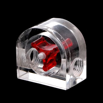
3.3.3 Paddle wheel flowmeter
A lower cost alternate to the turbine flowmeter is the paddle wheel flowmeter. This device is somewhat similar to the insertion type turbine flowmeter, but instead of a turbine blade with the flow generating lift forces to cause the rotation, the paddle wheel is perpendicular to the flow and rotates much like an old fashioned steam boat paddlewheel. These devices are usually inserted into a specially made tee in the flow line. The paddlewheel show in the photo, distributed by Omega, is shown inserted into its flow tee. The PVC fitting is then cemented onto two ¾” PVC pipes. In this size pipe, the meter is capable of reading flows from 1.7 to 34 gallons per minute to an accuracy of 1%. The sensor can also be used in pipe sizes from ½” to 36” in diameter for a flow range of 1 to nearly 7000 gallons per minute.
These transducers are extremely economical, running around $400 for the transducer. Like the turbine flowmeter, these also generate a pulse train generated by the paddles passing an internal pickup. The output is a frequency proportional to the flow rate. As with many flow measurement devices, this is also dependent on the stability of flow and significant turbulence will cause significant error. In general, the 20 / 10 rule should be followed to ensure that the flow is fully developed at the transducer location.
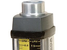
4.0 Variable Area flowmeters
There is a class of flow meters which use the pressure drop caused by an obstruction in the flow in a unique way. These meters, call variable area flow meters depend on the flow of the fluid to carry an object along. In a fixed diameter pipe, the object would be carried along with the flow based on the resistance to that flow. If the flow is moving in a variable diameter pipe, the force on that object changes with changes in the pipe diameter, and hence, the clearance between the sides of the object and the sides of the pipe. This class of flowmeters is generally represented by two main types; Rotameters and spring – plunger meters.
4.1 Rotameters
The rotameter is a variable area meter that employs a vertical tube of varying diameter, with an object inserted in it. This object is known as the float. This type meter is used only in a vertical position, as gravity is a primary force involved in the calibration of the device. The float is moved vertically in the variable diameter tube by a combination of buoyancy forces and flow pressure forces. The flow pressure forces are created by the fluid trying to move around the float, by using the gap between the float and the sides of the tube. As the forces move the float up the tube, the widening gap between the tube and the float allow these forces to be reduced, and gravity tends to force the float back down the tube toward the bottom. At the equilibrium point for a given flow, the forces of flow and buoyancy in the vertical direction are balanced by the mass of the float being pulled down by gravity.
https://mytoolsstore.com/product-category/measurement-analysis-instruments/flow-measuring-instruments/

Flow Measuring Instruments

Flow Measuring Instruments
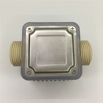
Computer PC Water Cooling System Water Flow Meter Speedometer Waterproof Sealing JUN20 dropship

Flow Measuring Instruments
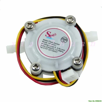
1pc Water Coffee Flow Sensor Switch Meter Flowmeter Counter 0.3-6L/min New
Flow Measuring Instruments
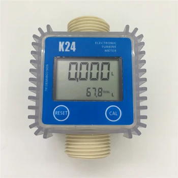
K24 Electronic Turbine flow meter Sensor for Diesel,urea,kerosene,gasoline, water,light oil

Flow Measuring Instruments
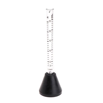
Argon Co2 Gas Flow Meter Peashooter Scale Tester Measure for Mig Tig Welder Welding
Flow Measuring Instruments


Flow Measuring Instruments
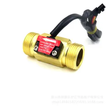
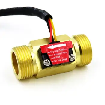
YF-B1 Copper G1/2″ DN15 thread Hall effect water liquid Flow Sensor Flow meter flowmeter 1~ 25L/MIN