Calipers, Measuring & Gauging Tools
Calipers

Dec
Calipers
A caliper (British spelling also calliper) is a device used to measure the distance between two symmetrically opposing sides. A caliper can be as simple as a compass with inward or outward-facing points. The tips of the caliper are adjusted to fit across the points to be measured, the caliper is then removed and the distance read by measuring between the tips with a measuring tool, such as a ruler.
They are used in the metalworking field of mechanical engineering, handloading, and in woodworking and woodturning.
Types

Fig. Two inside calipers
The inside calipers on the right are used to measure the internal size of an object.
The upper caliper in the image (at the right) requires manual adjustment prior to fitting, fine setting of this caliper type is performed by tapping the caliper legs lightly on a handy surface until they will almost pass over the object. A light push against the resistance of the central pivot screw then spreads the legs to the correct dimension and provides the required, consistent feel that ensures a repeatable measurement.
The lower caliper in the image has an adjusting screw that permits it to be carefully adjusted without removal of the tool from the workpiece.
Outside caliper

Fig. Three outside calipers.
Outside calipers are used to measure the external size of an object.
The same observations and technique apply to this type of caliper, as for the above Inside caliper. With some understanding of their limitations and usage these instruments can provide a high degree of accuracy and repeatability. They are especially useful when measuring over very large distances, consider if the calipers are used to measure a large diameter pipe. A vernier caliper does not have the depth capacity to straddle this large diameter while at the same time reach the outermost points of the pipes diameter.
Divider caliper

Fig. A pair of dividers
In the metalworking field divider calipers are used in the process of marking out suitable workpieces. The points are sharpened so that they act as scribers, one leg can then be placed in the dimple created by a center or prick punch and the other leg pivoted so that it scribes a line on the workpiece’s surface, thus forming an arc or circle.
A divider caliper is also used to measure a distance between two points on a map. The two caliper’s ends are brought to the two points whose distance is being measured. The caliper’s opening is then either measured on a separate ruler and then converted to the actual distance, or it is measured directly on a scale drawn on the map. On a nautical chart the distance is often measured on the latitude
scale appearing on the sides of the map: one minute of arc of latitude is approximately one nautical mile or 1852 metres.
Oddleg caliper

Fig. Odd leg calipers
Oddleg calipers, Hermaphrodite calipers or Oddleg jennys, as pictured at left, are generally used to scribe a line a set distance from the edge of workpiece. The bent leg is used to run along the workpiece edge while the scriber makes its mark at a predetermined distance, this ensures a line parallel to the edge.
In the diagram at left, the uppermost caliper has a slight shoulder in the bent leg allowing it to sit on the edge more securely, the lower caliper lacks this feature but has a renewable scriber that can be adjusted for wear, as well as being replaced when excessively worn.

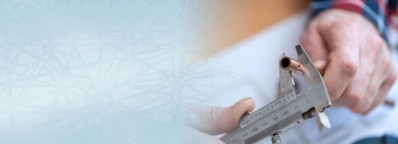
Fig. Parts of a vernier caliper:
Outside jaws: used to measure external lengths Inside jaws: used to measure internal lengths Depth probe: used to measure depths
Main scale (cm)
Main scale (inch)
Vernier (cm)
Vernier (inch)
Retainer: used to block movable part to allow the easy transferring a measurement

Fig. A vernier caliper
A variation to the more traditional caliper is the inclusion of a vernier scale; this makes it possible to directly obtain a more precise measurement.
Vernier calipers can measure internal dimensions (using the uppermost jaws in the picture at right), external dimensions using the pictured lower jaws, and depending on the manufacturer, depth measurements by the use of a probe that is attached to the movable head and slides along the centre of the body. This probe is slender and can get into deep grooves that may prove difficult for other measuring tools.
The vernier scales will often include both metric and Imperial measurements on the upper and lower part of the scale.
Vernier calipers commonly used in industry provide a precision to a hundredth of a millimetre (10 micrometres), or one thousandth of an inch.
A more accurate instrument used for the same purpose is the micrometer.

Fig. Mitutoyo dial caliper
A further refinement to the vernier caliper is the dial caliper.
In this instrument, a small gear rack drives a pointer on a circular dial. Typically, the pointer rotates once every inch, tenth of an inch, or 10 millimetres, allowing for a direct reading without the need to read a vernier scale (although one still needs to add the basic inches or tens of millimeters value read from the slide of the caliper). The dial is usually arranged to be rotatable beneath the pointer, allowing for “differential” measurements (the measuring of the difference in size between two objects, or the setting of the dial using a master object and subsequently being able to read directly the plus-or-minus variance in size of subsequent objects relative to the master object).
The slide of a dial caliper can usually be locked at a setting using a small lever or screw; this allows simple go/no-go checks of part sizes.

Fig. Digital caliper
A refinement now popular is the replacement of the analog dial with an electronic digital display. This version of the caliper allows reading the value directly from a single display. Many digital calipers can be switched between metric and imperial units. All provide for zeroing the display at any point along the slide, allowing the same sort of differential measurements as with the dial caliper but without the need to read numbers that may be upside down. Digital calipers may contain some sort of “reading hold” feature, allowing the reading of dimensions even in awkward locations where the display cannot be seen.
With all of these benefits, digital calipers have by no means replaced the dial caliper. Digital calipers typically do not have the beam structure of a dial or vernier caliper and therefore do not have the repeatablility or accuracy to an amateur user. Dial calipers have the potential to last much longer with their repairability.[citation needed]
Increasingly, digital calipers offer a serial data output to allow them to be interfaced with a personal computer. This means measurements can be taken and instantly stored in a spreadsheet or similar piece of software, significantly decreasing the time taken to take and record a series of measurements. The output of non-name brand calipers is usually 24 bit 90 kHz synchronous. A suitable interface to convert the output to RS232 levels and format can be built or purchased.
Like dial calipers, the slide of a digital caliper can usually be locked using a lever or thumb-screw.
Both dial and digital calipers can be used with accessories that extend their usefulness. Examples are a base that extends their usefulness as a depth gauge and a jaw attachment that allows measuring the center distance between holes.
Use

Fig. Using the vernier caliper
A caliper must be properly applied against the part in order to take the desired measurement. For example, when measuring the thickness of a plate a vernier caliper must be held at right angles to the piece. Some practice may be needed to measure round or irregular objects correctly.
Accuracy of measurement when using a caliper is highly dependent on the skill of the operator. Regardless of type, a caliper’s jaws must be forced into contact with the part being measured. As both part and caliper are always to some extent elastic, the amount of force used affects the indication. A consistent, firm touch is correct. Too much force results in an underindication as part and tool distort; too little force gives insufficient contact and an overindication. This is a greater problem with a caliper incorporating a wheel, which lends mechanical advantage. This is especially the case with digital calipers, calipers out of adjustment, or calipers with a poor quality beam.
Simple calipers are uncalibrated; the measurement taken must be compared against a scale. Whether the scale is part of the caliper or not, all analog calipers.
— verniers and dials — require good eyesight in order to achieve the highest precision. Digital calipers have the advantage in this area.
Calibrated calipers may be mishandled, leading to loss of zero. When a calipers’ jaws are fully closed, it should of course indicate zero. If it does not, it must be recalibrated or repaired. It might seem that a vernier caliper cannot get out of calibration but a drop or knock can be enough. Digital calipers have zero set buttons.

Fig. A set of vernier calipers.
A vernier scale lets one read more precisely from an evenly divided straight or circular measurement scale. It is fitted with a sliding secondary scale that is used to indicate where the measurement lies when it is in-between two of the marks on the main scale.
It was invented in its modern form in 1631 by the French mathematician Pierre Vernier (1580–1637). In some languages, this device is called a nonius, which is the Latin name of the Portuguese astronomer and mathematician Pedro Nunes (1492–1578) who invented the principle. Another theory is that this name is from the Latin “nona” meaning “9” and therefore “nonius” means a “ninth” of the main scale.
Verniers are common on sextants used in navigation, scientific instruments and machinists‘ measuring tools (all sorts, but especially calipers and micrometers) and on theodolites used in surveying.
When a measurement is taken by mechanical means using one of the above mentioned instruments, the measure is read off a finely marked data scale (the “fixed” scale, in the diagram). The measure taken will usually be between two of the smallest gradations on this scale. The indicating scale (“vernier” in the diagram) is used to provide an even finer additional level of precision without resorting to estimation.(1.2)

An enlarged view of the above calipers shows they have a resolution or precision of 0.02 mm. The reading is 3.58 mm. The 3 mm is read off from the upper (fixed) data scale. The 0.58 mm is obtained from the lower (sliding) indicating scale at the point of closest alignment between the two scales. The superimposed red markings show where the readings are taken. Note In this example it is not clear whether the right value is 0.58 mm or 0.60 mm
Construction
The indicating scale is constructed so that when its zero point is coincident with the start of the data scale, its gradations are at a slightly smaller spacing than those on the data scale and so do not coincide with any on the data scale. N gradations of the indicating scale would cover N-1 gradations of the data scale (where N is the number of divisions the maker wishes to show at the finer level).
Use

Fig. Animation of a caliper measurement using a vernier scale. Click to enlarge
When a length is measured the zero point on the indicating scale is the actual point of measurement, however this is likely to be between two data scale points. The indicator scale measurement which corresponds to the best-aligned pair of indicator and data gradations yields the value of the finer additional precision digit.
Examples
On instruments using decimal measure, as shown in the diagram below, the indicating scale would have 10 gradations covering the same length as 9 on the data scale. Note that the vernier’s 10th gradation is omitted.
On an instrument providing angular measure, the data scale could be in half- degrees with an indicator scale providing 30 1-minute gradations (spanning 29 of the half-degree gradations).
Why a vernier scale works
The vernier scale is constructed so that it is spaced at a constant fraction of the fixed main scale. So for a decimal measuring device each mark on the vernier would be spaced nine tenths of those on the main scale. If you put the two scales together with zero points aligned then the first mark on the vernier scale will be one tenth short of the first main scale mark, the second two tenths short and so on up to the ninth mark which would be misaligned by nine tenths. Only when a full ten marks have been counted would there be an alignment because the tenth